WRO 2026 Hat
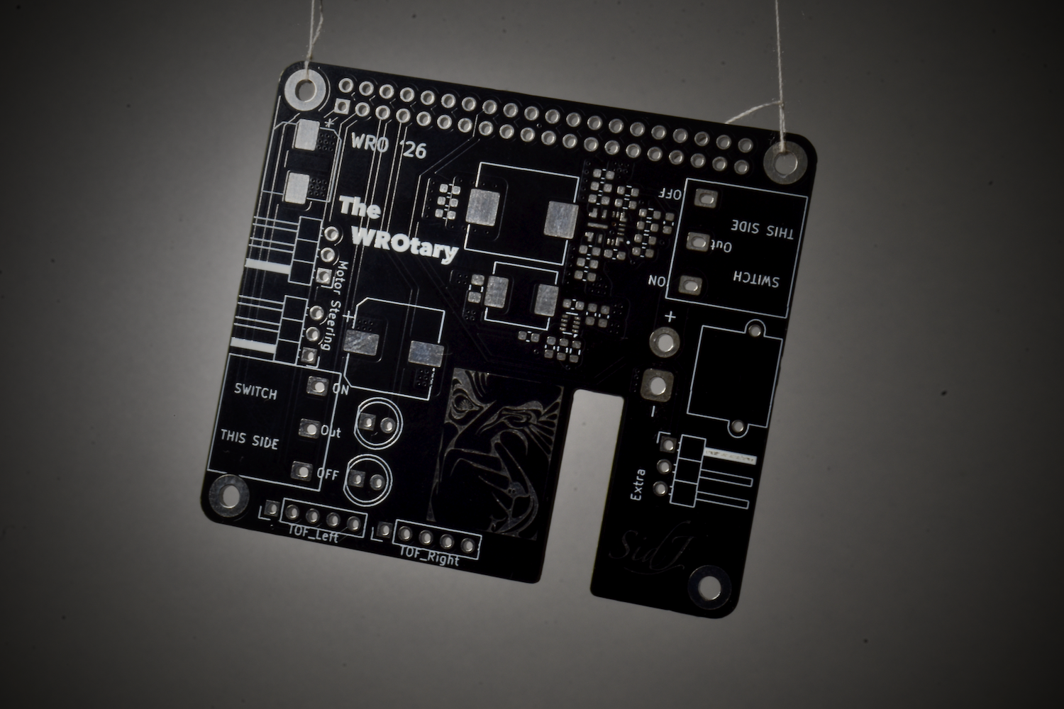
The buildup to this board has been quite substantial. I had the SD card under volt on the Raspberry Pi last year. To fix this, I dove into PCBA. The last board I made was a custom buck converter featuring the TI LM61460 that had an output of 5.15V and headroom for 6A. This was a stand alone module. The end goal always was to have an integrated and compact solution that would be scalable. For WRO 2025, I had a hat that sat on top of the Raspberry Pi and provided 5V to the Pi and 8V to the servo using off the shelf modules. I really liked that form factor so I decided to keep it. Everything else was engineered to be better, taking learning from the previous year. I had the following requirements for the hat: - Deliver 5.15V to the Raspberry Pi and have a continuous rating of at least 3-5A to power the LiDAR as well. - Deliver 8V to the servo motor at 2A. - Provide a better hardware interface between the IO pins of the Pi and the motors and sensors. - Integrate the power switch and start switch, along with indicator LEDs needed for the rules on to the board. Building on a successful 2-layer buck converter module, I chose the LM61460 as the buck converter for the 5.15V rail and chose the TPS62932 from TI as the buck converter for the 8V rail. You can find more details about the design process in the Engineering Manual for the competition here. I cover the thought process and decision making in section 2. I made a lot of improvements over last year's hat. Instead of having screw terminals as the interface for power, I switched to the XT30 connector. I also added mounting holes for M2.5 screws, something that was absent last year. This would be the first time I assembled the boards myself, as the custom buck converter I had made was assembled by JLCPCB. I sent the design files to JLC for production. This was the first 4 layer board I had designed. The first step to assembly was applying the solder paste. For this, I securely mounted the PCB on a piece of ply wood and added 4 more PCBs around it to constrain it in place. Then, I stuck the stencil over it and used a scraper to apply the paste. I then used my mom's microscope (thanks mom) to inspect the paste application. Then I placed the components on to the board using tweezers. The most nerve racking part was ensuring proper alignment, but I soon was able to do it without thinking about it too much. The first iteration, V1.0, had a fatal flaw. During the schematic design, the enable pin of the LM61460 was connected to ground. The enable pin needs a voltage of greater than about 3V. This meant that the chip would be in the "shutdown mode" and it would not work at all. Ordering a new board meant a 15-day transit delay and significant shipping costs. So I opted to try and repair the board first. To fix the board, I first cut the trace that connected GND to the EN pin. The next step was to bridge the EN and VIN pins. The microscopic pins of the VQFN package meant that I could not solder a wire externally. The only option was to add a wire underneath the IC and hope that would connect and work. I tried the fix with a 32AWG copper wire, the smallest I had laying around. But the flat pins of the VQFN package got me again. While the wire was fairly thin, its thickness meant that not all the pins of the IC made contact with the PCB. It was like a see-saw. Another attempt was made with a thinner strand of wire, but that led to the same outcome. Hence, a revision was needed and V1.1 was put in place. The board had passed exhaustive bench testing and easily survived its first dozen battery power-cycles. On powering it for twelfth or so time, the LM61460 IC violently self destructed. It turns out the catastrophic failure was driven by an undamped LC hot-plug transient. The battery wires' parasitic inductance and the board's ultra-low Equivalent Series Resistance (ESR) ceramic input capacitors formed an aggressive resonant tank. When the mechanical power switch was toggled, microscopic contact bounce combined with the near-zero resistance of the ceramic caps to trigger a violent inrush current ringing. This transient spiked the voltage past double the 16.8V battery input, instantly shattering the LM61460's 36V absolute maximum rating. This spike was further supercharged by the DC bias derating of the ceramic capacitors, which shed capacitance under high voltage and drove the transient even higher. To tame the parasitic resonance, a 1000 uF electrolytic capacitor was wired between the switch output and ground. The component's native, higher ESR acted as an integrated shock absorber, safely dissipating the inrush kinetic energy as microscopic heat, choking out the LC ringing, and bulletproofing the input rail against future switch bounce. After this fix, the board did not have any issues. Ultimately, I learnt a lot from this experience. I really learnt how to leverage pours (you can now call me "copper pour pilled" I guess) and helped me understand proper check measures. I also learnt how to assemble boards myself and I found the process to be therapeutic. I was using 0603 capacitors and resistors, so I guess it wasn't that bad. I don't think I would change the design in any way (apart from adding a snubbing capacitor directly across the switch) if I were to redesign the board again. I really hate leaving the boards bare. I always add quotes or art work on the silkscreen, on the top and bottom for fun. This board features art work by M.C. Escher. It features "Perfume" on the front side in the surface finish and "Stars" on the back in silkscreen. You can find more pictures I took below!