Custom Buck Converter
During the 2025 WRO Future Engineers competition, we were disqualified because the data on our Raspberry Pi became corrupted and the SD card failed.
Months later, I analyzed the output voltage of the 5V, 5A-rated buck converter we had been using. I discovered that the Raspberry Pi was constantly undervolting under load. We had attempted to add a capacitor before the competition to resolve the issue, but the effort proved futile. Upon reviewing the logs, I confirmed that these undervoltage events were, in fact, what caused the SD card to fail.
I searched the market for a buck converter capable of providing the 5.1V required by the Raspberry Pi to prevent undervolting, but I couldn't find a suitable option. Consequently, I decided to design my own.
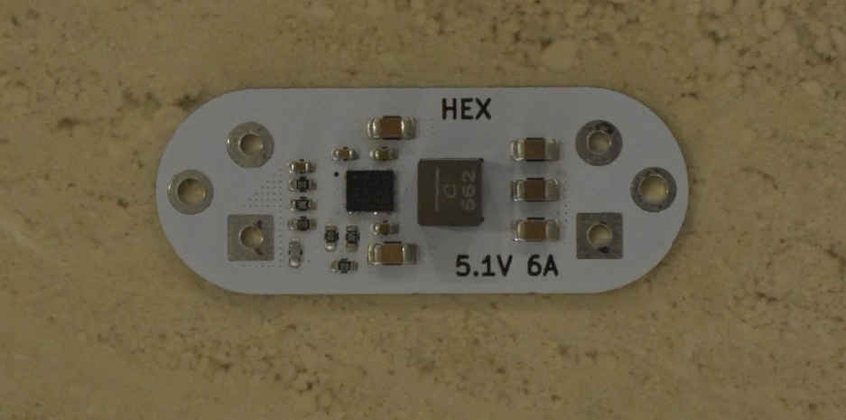
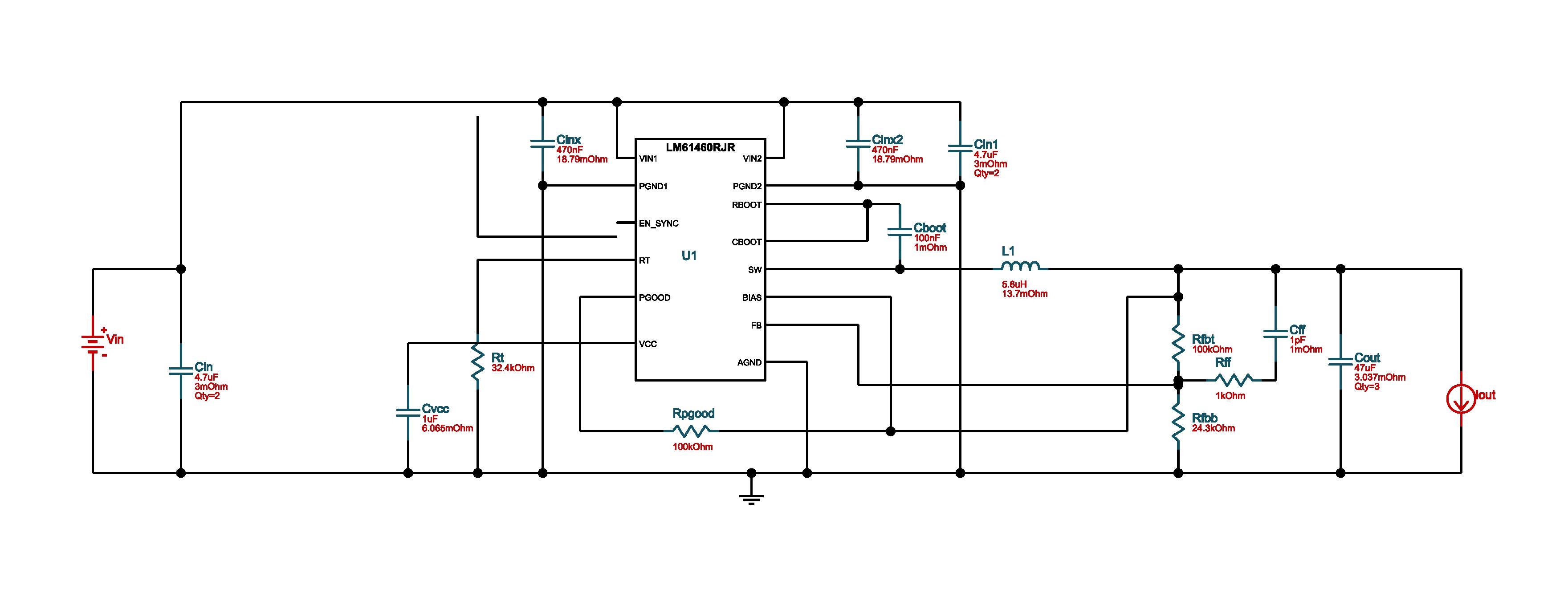
Using the TI LM61460, I designed a buck converter in KiCAD that accepts a 3S-6S battery input and outputs a steady 5.1V at 5A continuous. Due to the small physical size of the IC, I had to incorporate extensive thermal management into the PCB layout.
I had the PCB fabricated and assembled by JLCPCB, and I am very happy with the results. I stress-tested the converter at 5A for eight hours, and it performed flawlessly without any issues
Project Gallery